VEX Gripper Robot
RBE 1001 Final Project
8.24.2022 - 9.13.2022 | WPI
OBJECTIVE
The project was in the form of the game with the objective to score as many points as possible. The main objective was reaching the max 32 points however possible by collecting/delivering balls through different height of ports, climbing the ramp, and parking. We chose to tackle this by focusing primarily on delivering red balls, climbing the ramp autonomously and parking in tele-op.

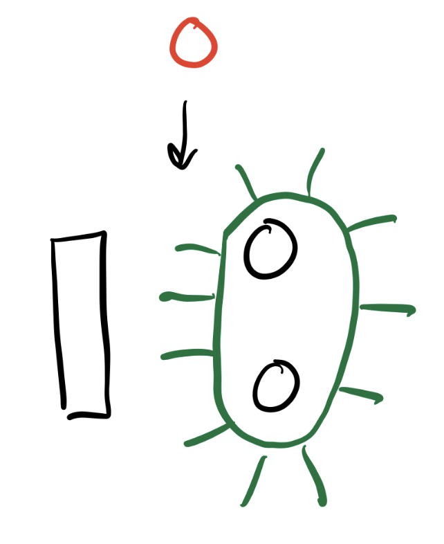
Illustration of the game arena (source: WPI RBE dept)
GAME RULES & RESTRICTIONS
-
TASK POINTS
Delivering a red/blue ball Auto: 4 Tele-op: 2
Collecting a yellow ball Auto: 8 Tele-op: 4
———————————————————————————————
MAX POINTS FOR BALL DELIVERY Auto: 16 Tele-op: 10
———————————————————————————————
Climbing ramp Auto: 4 Tele-op: 1
Crossing to the other side Auto: 4 Tele-op: 1
Parking Auto: 4 Tele-op: 1
———————————————————————————————
TOTAL MAX POINTS Auto: 20 Tele-op: 12
-
• Any combination of ball delivery is allowed to achieve the max points
1 red + 3 blue = 16 (auto) | 3 red + 1 yellow = 10 (tele-op)
• A team may at any time add additional red or blue balls to the arena, but they must be placed in the corner zone, but only when no robot is in the corner zone
• The robot must climb the ramp, either in auto or tele-op. A successful climb is defined as fully traveling at least 6" up the steepest part of the ramp with at least part of the robot within 2 inches of the plexiglass divider.
• Teams have 10 minutes to complete as many tasks as needed to collect points
• When operating in autonomous mode, teams will not be allowed to interfere with it once the robot has started
Restarting is allowed as many times as needed within the time limit, but scores are not cumulative
-
• A robot may only fully support (i.e. lift/carry) up to five balls at a time
• The nominal dimensions of the robot at the start of each match may not exceed 15.25” x 15.25” x 18.75”
• The robot’s weight must not exceed 10.0 lbs
• Gaining traction by use of adhesives or by abrading or breaking the surface of the playing field is not allowed
• Each team will be expected to use parts only from the RBE1001 VEX lab kits, plus custom parts that they design and produce using the WPI Maker Spaces (e.g., 3d printing, laser cutting, etc.).
• Only one battery may be used on the robot at a time
• Over size, over weight limit and failure to climb ramp will deduct 2 points each
CORE FUNCTIONALITY
Ball Detection
Camera vision sensor was used to detect the position and the color of the balls as the ultrasonic sensor did not reflect well off the balls.
Ball Intake
Horizontal spinner was attached to the end of an arm with 2 degrees of freedom that took care of intaking the balls, and was able to hold two balls at maximum.
Navigation
Line sensors and the ultrasonic sensors were implemented to follow the lines, detect intersections to make turns, and to position an appropriate distance away from the port. Some dead reckoning was used to keep the robot on the line after the ball was picked up.
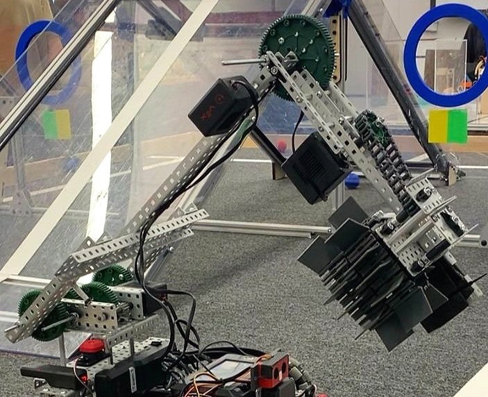
Ball Delivery / Out-take
The arm positions itself to the right height of the port and the horizontal spinner spins outward to spit the balls back out through the port.
Ramp Climb
Omni wheels were used instead of regular wheels and the four wheel drive system was implemented, interconnecting the wheels using chains, to provide more power. The arm was extended in a climbing mode to keep the center of mass relatively in the front.
Parking
A small plate was mounted to the front of the arm to serve as a hook to hook onto the wall after the power was shut down.

DESIGN PROTOTYPING
BALL INTAKE
IDEAS
Claw-like gripper: required too much precision and accuracy, slow operation time
Horizontal roller bar / funnels: fast and not much precision needed, but difficult to integrate with the delivery system
FINAL IMPELMENTATION
Spinner: relatively not much precision required, fairly fast and robust with “all in one” system for intaking and out-taking the balls


final implementation
BALL OUT-TAKE
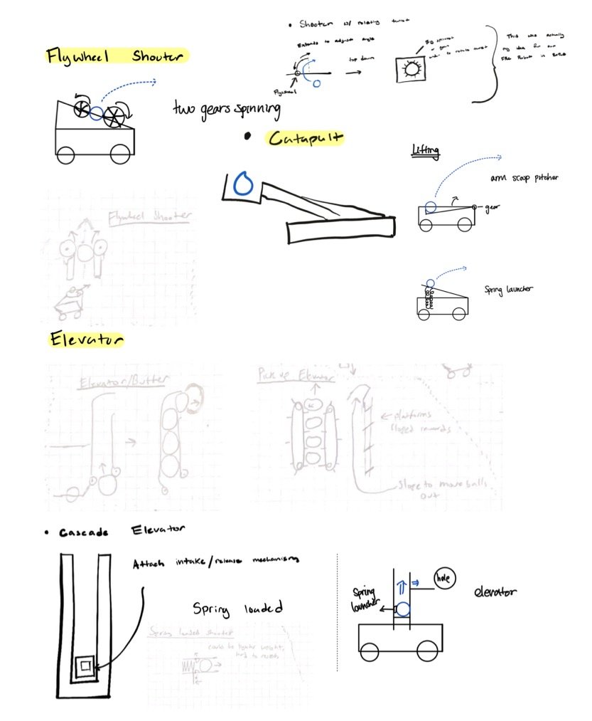
IDEAS
Flywheel shooter / Catapult: accurate calculation required for the trajectory of the ball. Inconsistency in speed of Vex motors might lead to inconsistency of the trajectory
Elevator: complicated design for a limited time, not much flexibility in mobility
FINAL IMPELMENTATION
Spinner arm: easiest and simplest to implement and worked well in terms of reaching a desired height.
final implementation
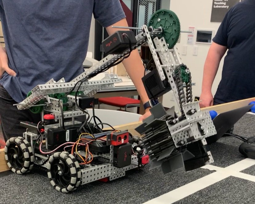
SYSTEM DESIGN / INTEGRATION
Our final system consisted of only one core overarching mechanism, the arm. We had an arm with two degrees of freedom (a shoulder and an elbow joint). Attached to the end of the arm was a horizontal spinner intake powered by a motor sitting on the “forearm” of the robot. The spinner had one active side consisting of a spinning belt with rubber flaps attached to it to grip the balls into the other passive side consisting of a metal wall with foam attached to it for friction.


Our navigation needed to be robust as the ports for delivering the balls were relatively small. Our initial plan was to use the camera only to detect the ports and use an accumulator to tell which side of the field it was on, however, it quickly got complicated and required a lot of effort to make it work well. We ended up using line sensors to follow the line to navigate near the port and used an ultrasonic sensor to stop at an accurate distance away from the port. Additionally, after it had gone off the line to pick up the ball, dead reckoning was used until it had detected the linen to follow again.
CHALLENGES
Weight & Size limitation
Due to a low precision of our intake mechanism using the horizontal spinner, we ended up adding another spinner right below to widen our surface area of spinner so the balls could get in more easily. However, this added additional weights to our robot where we had to take off our h-drive wheel to meet the weight requirement. Furthermore, most of our weights were concentrated in the arm which unbalanced the center of mass, causing the robot to tilt forward when driving backwards.
We had to change out the gear in our elbow join, since it required a higher torque to bear the weight of the spinner. We ended up switching out all the gears in the arm joints for a larger gear to provide more torque to the system for more sturdiness.
Ball Detection
Since the vision detection heavily relies on brightness of the object and the background, when we did not have the same lighting or background as when we have calibrated them, the robot’s position would be off by a small-scale which sometimes led to failure of grabbing the ball properly and shooting them out.
We made sure that the camera was calibrated occasionally to ensure consistency and tried to provide a constant background by removing covering any red objects and holding up black fabric in the background.
Navigation
Our robot sometimes had trouble adjusting its position, where if the robot arrived near the targeted position at a slight angle that is off the line, it would turn slightly at the end to adjust for the line sensor which would end up messing up at the shooting angle. Since our autonomous system used a manual turn of 180 degrees, the slight error that occurred in the first loop would accumulate, causing it to be significantly off by the fourth or the fifth loop of our trials.
To resolve this, our proportional and integral control values for line sensors, the ultrasonic sensor turn-angles were tweaked around according to our environment for the best performance.